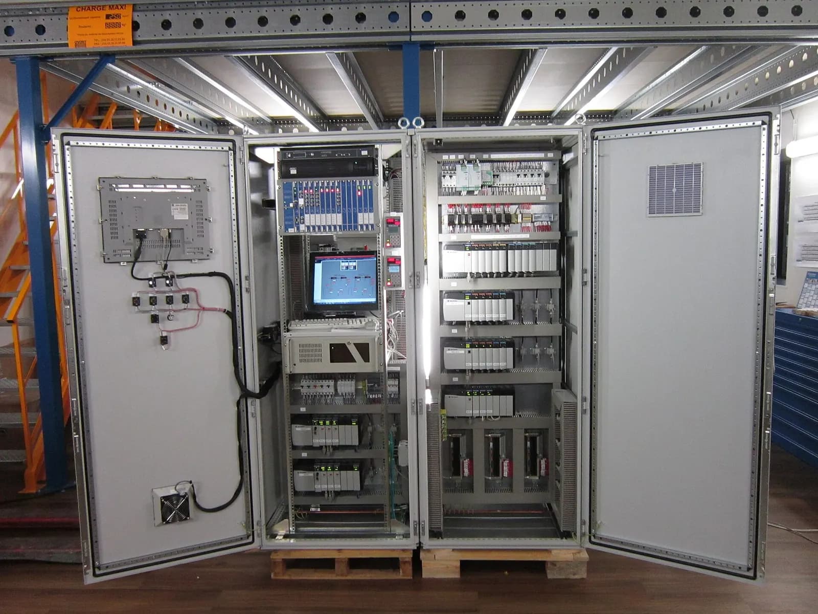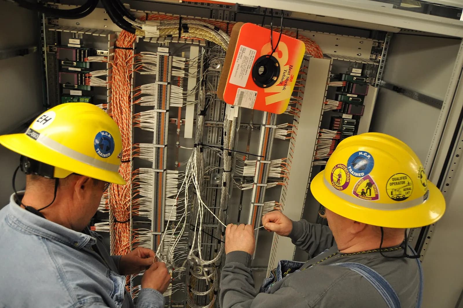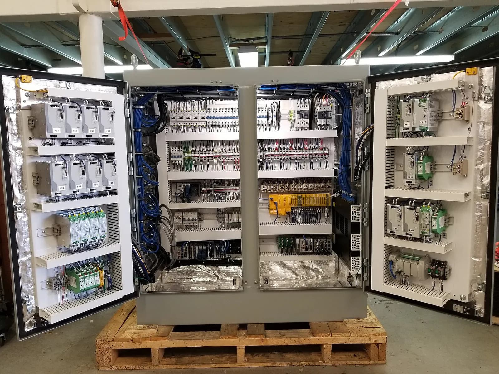
Control panel schematic drawings are the sheet set a panel builder wires from and a maintenance electrician fault-finds from: power distribution, the 24 V control supply, every PLC input and output card, the safety circuit and the panel layout. LADX CAD is a 2D drafting tool that opens on a finished set of these sheets rather than a blank one, fills the title block from the project, and exports DXF for whoever builds the panel.
This article sets out what a complete set should contain for a UK machine or process panel, how the LADX tool works step by step, and the gaps you should plan around. LADX is the Wartens group's AI product for controls teams.
What a control panel schematic set should contain
Sheet order matters. A set numbered the way it is read lets an electrician go from a fault on the HMI to the right terminal in minutes. LADX CAD ships eleven working templates in that reading order:
| Sheet | What it shows | Who leans on it |
|---|---|---|
| Cover, index, symbol legend | Project, revision, sheet list, symbols | Everyone, first |
| Power distribution | Incoming supply, isolator, protective devices | Panel builder, inspector |
| 24 V control supply | PSU, fusing, 0 V distribution | Panel builder |
| PLC digital inputs and outputs | Field device, terminal, card channel | Commissioning, maintenance |
| PLC analogue I/O | Loop power, shielding, ranges | Instrument technician |
| Safety circuit | E-stops, safety relay or PLC, contactors | Safety reviewer |
| Panel GA and terminal schedule | Layout, cut-outs, terminal numbering | Panel shop, installer |
For machinery, the content of that set is not a matter of taste. IEC 60204-1, published in the UK as BS EN 60204-1, sets requirements for the documentation supplied with the electrical equipment of machines, including the diagrams needed for installation, operation and maintenance. Our BS EN 60204-1 guide covers the clauses that cause most problems on UK machines.
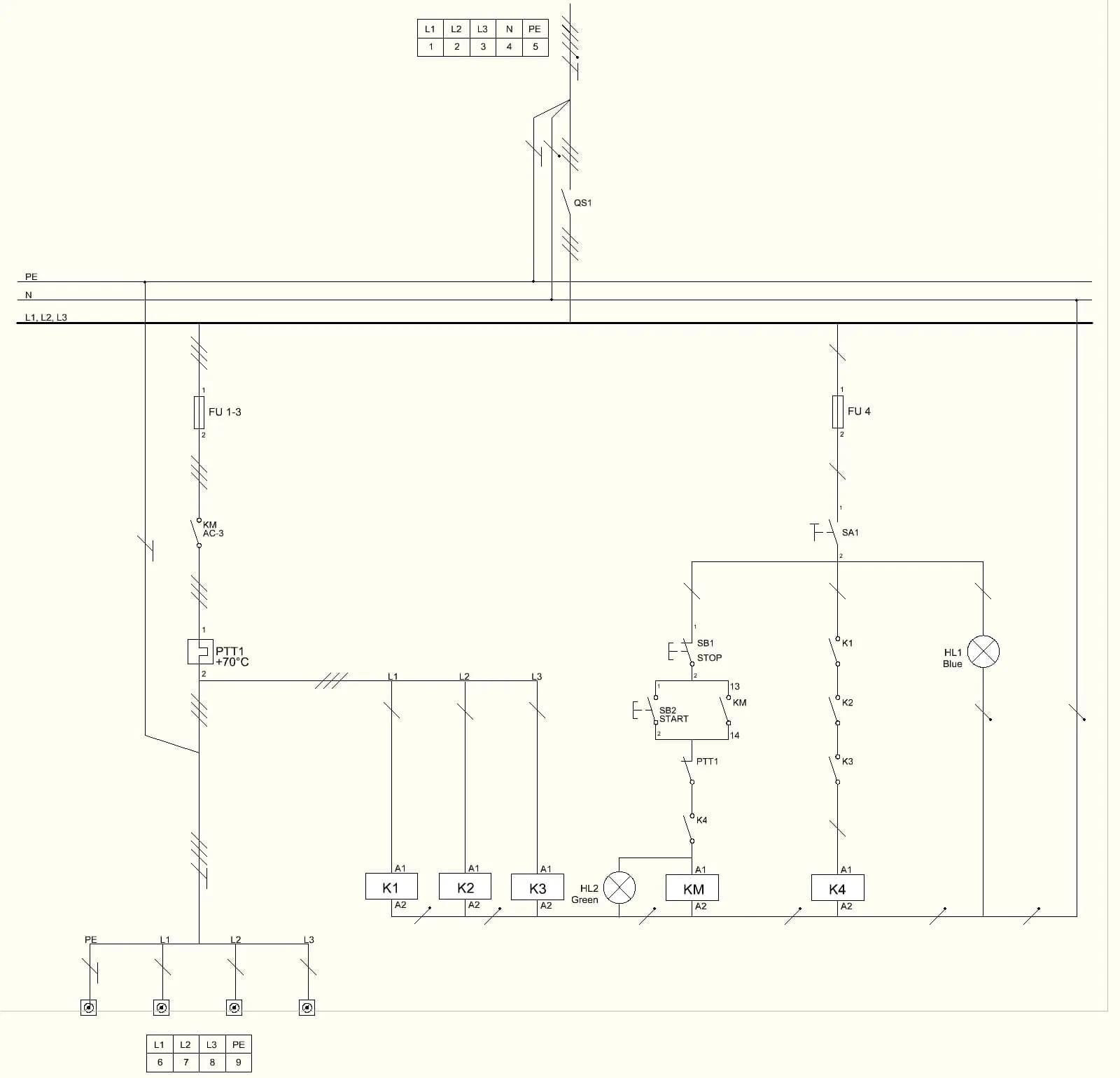
How LADX CAD drafts the set, step by step
- File the drawing against a project. The project already holds the client, site, project number and date, so the title block fills itself on every sheet. Change the project and every sheet follows.
- Start from the template sheets. Each one opens with rails, conventions and border already drawn. You edit a working sheet instead of rebuilding a standard sheet for the hundredth time.
- Draft with typed commands. There are thirty-four, with aliases such as L, REC, C, TR, EX, O, F, CO, M and H, and coordinates in absolute, relative and distance-with-angle forms. Object snap, dimensions, leaders and a measure tool are there for the panel GA.
- Edit like a drafter. Trim, extend, offset, fillet, rectangular and polar arrays, mirror, rotate, scale and hatch cover most schematic and layout work.
- Export as DXF. The interchange format is DXF R12 ASCII, documented in Autodesk's DXF reference archive, which most CAD tools used by UK panel builders can open.
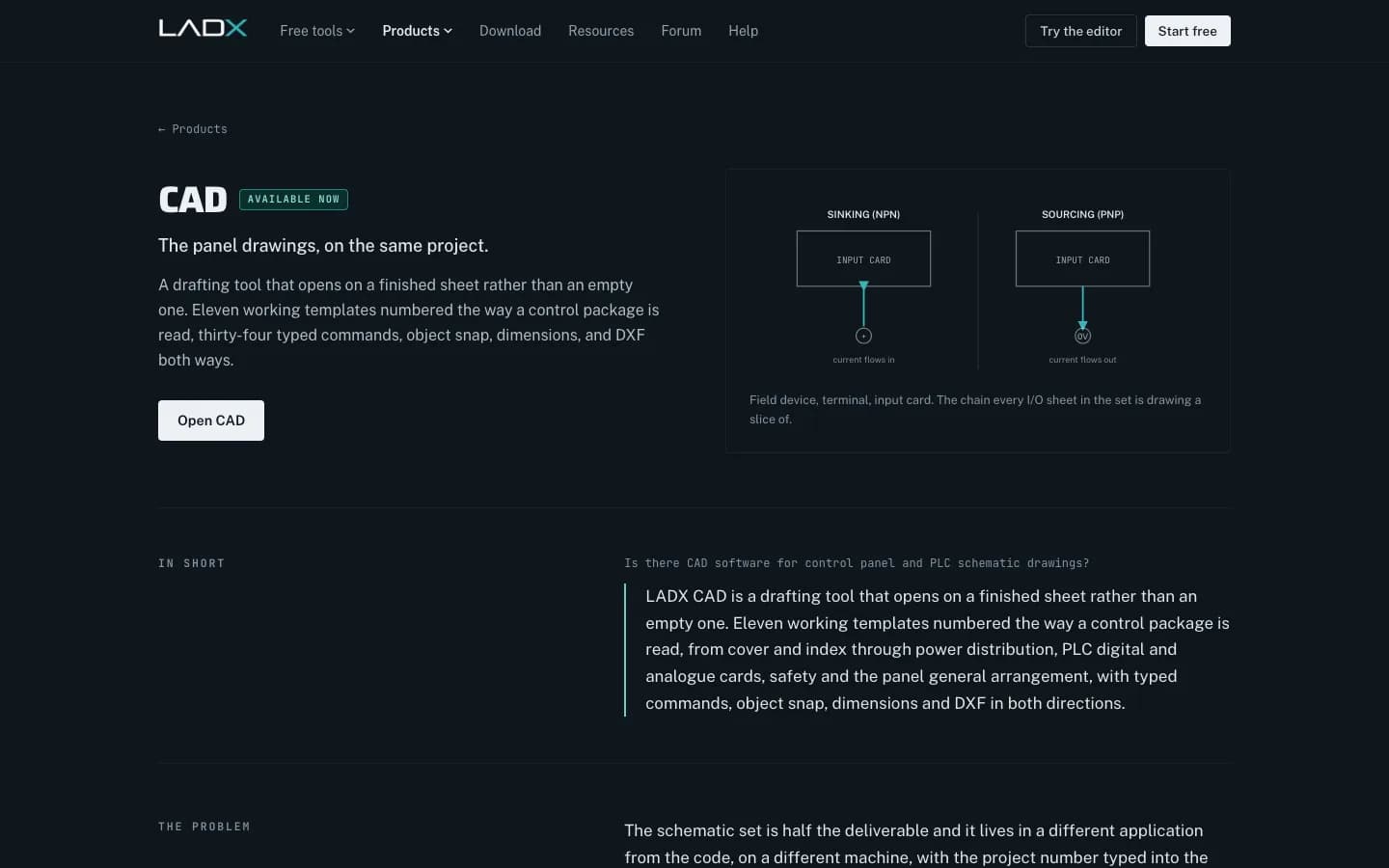
Sinking, sourcing and other details the drawings must settle
The I/O sheets are where design decisions become wires. Decide early whether input cards are sinking (current flows in) or sourcing (current flows out) and draw every field device that way, because mixing the two on one card is a classic first-day commissioning fault. Show the terminal number, card slot and channel on every device, and keep 0 V and shield terminations explicit on analogue sheets.
On water company work, expect the client's own drawing standard to override general practice on symbols, numbering and title blocks. Get the current revision before the first sheet is drawn; it is cheaper than redrawing forty sheets at FAT.
What LADX CAD does not do
- It is two-dimensional only. There is no 3D panel modelling and none is planned.
- DXF is the bridge. A DWG has to be exported to DXF from whatever wrote it. The product page describes DXF in both directions, while its FAQ says export works today and import is on the plan, so check the current state before you count on opening an existing panel builder's drawings.
- It does not do electrical design checks. It draws what you tell it and will not check that a breaker is rated for the load or that cable sizes suit the protective device.
- It is not yet linked to the PLC tag table. The I/O templates and the tags sit in the same project, but the line between them is still drawn by hand. LADX calls this the most valuable thing to add.
In practice that means LADX CAD suits small and medium control packages, retrofit panels and teams who want drawings, code and documents in one place. Large panel shops with a full electrical CAD suite and parts database will keep using it, and can still take DXF from you.
How to Read Electrical Diagrams | Wiring Diagrams Explained | Control Panel Wiring Diagram
Upmation
This video is hosted on YouTube. Playing it loads content from Google, which may set cookies.
Watch on YouTubeHow this fits a real UK project
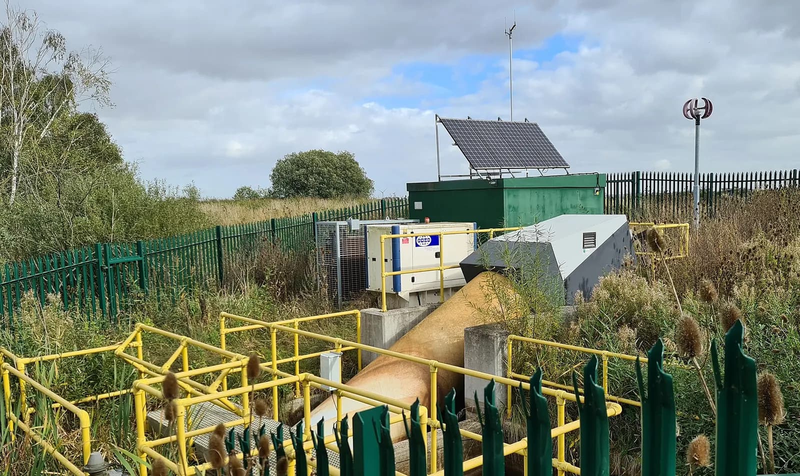
On a sewage pumping station refurbishment, for example, the set might be twelve sheets: power, control supply, two digital input sheets for level switches and pump feedback, outputs to the starters, an analogue sheet for the level transmitter, the telemetry outstation interface and the GA. Our guide to pumping station control panel upgrades shows what that panel needs to do. Drafting the sheets on the same project as the program means the I/O list, the drawing and the code are less likely to disagree at FAT.
Wartens produces schematic sets, PLC software and test documents for UK clients as part of our PLC and SCADA engineering service, using the client's drawing standard and CAD format where one is specified.
Next step
Try the CAD templates on ladx.ai with one of your own panels. If you need a full drawing set and PLC program for a UK panel, send the I/O list and any existing drawings to our team through the contact page for a written scope and price.