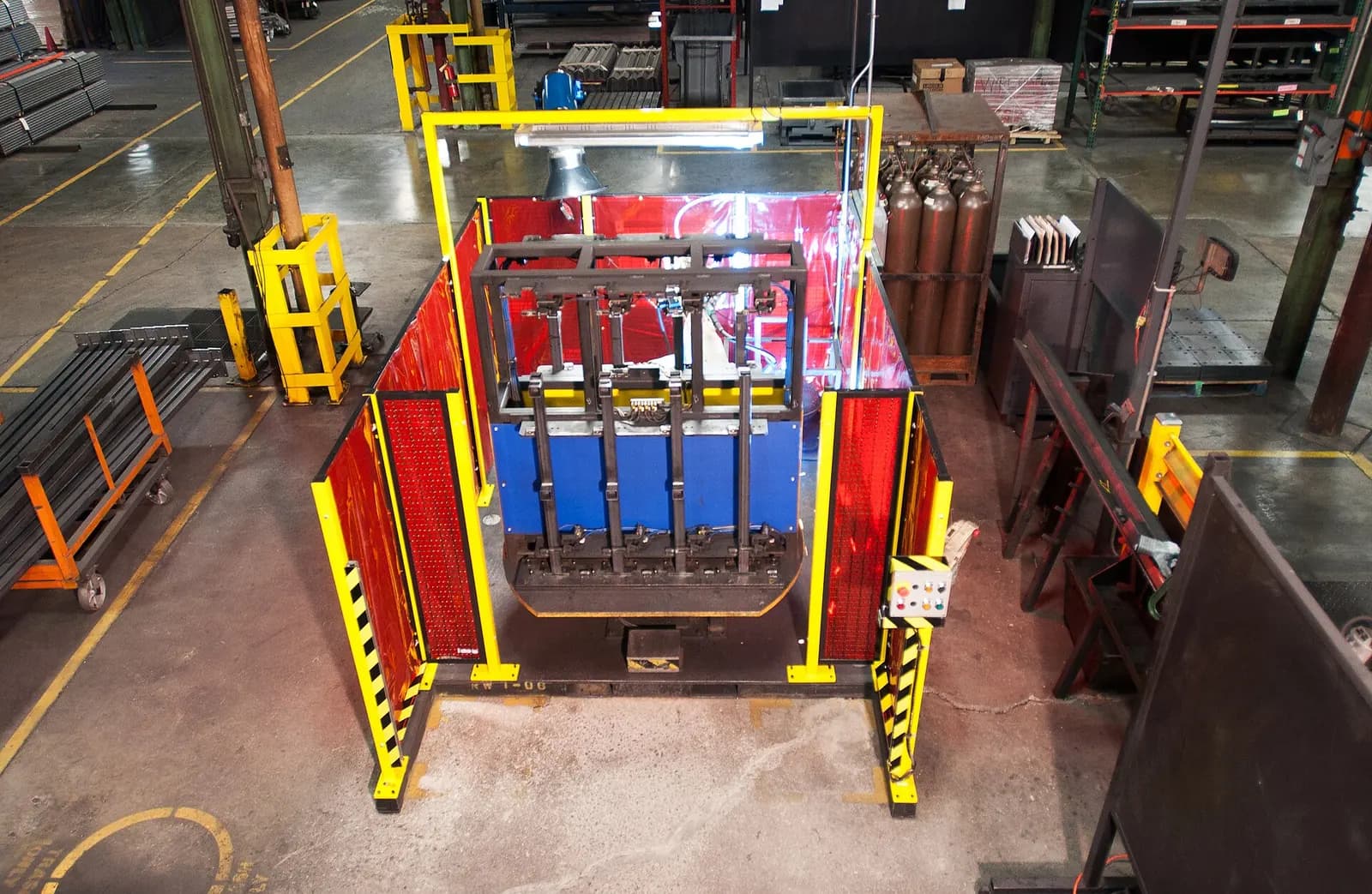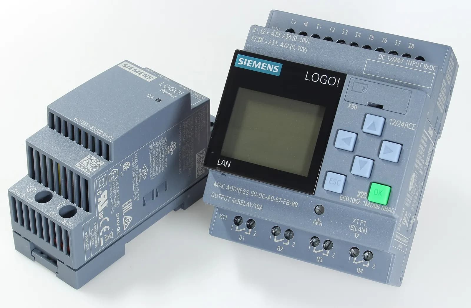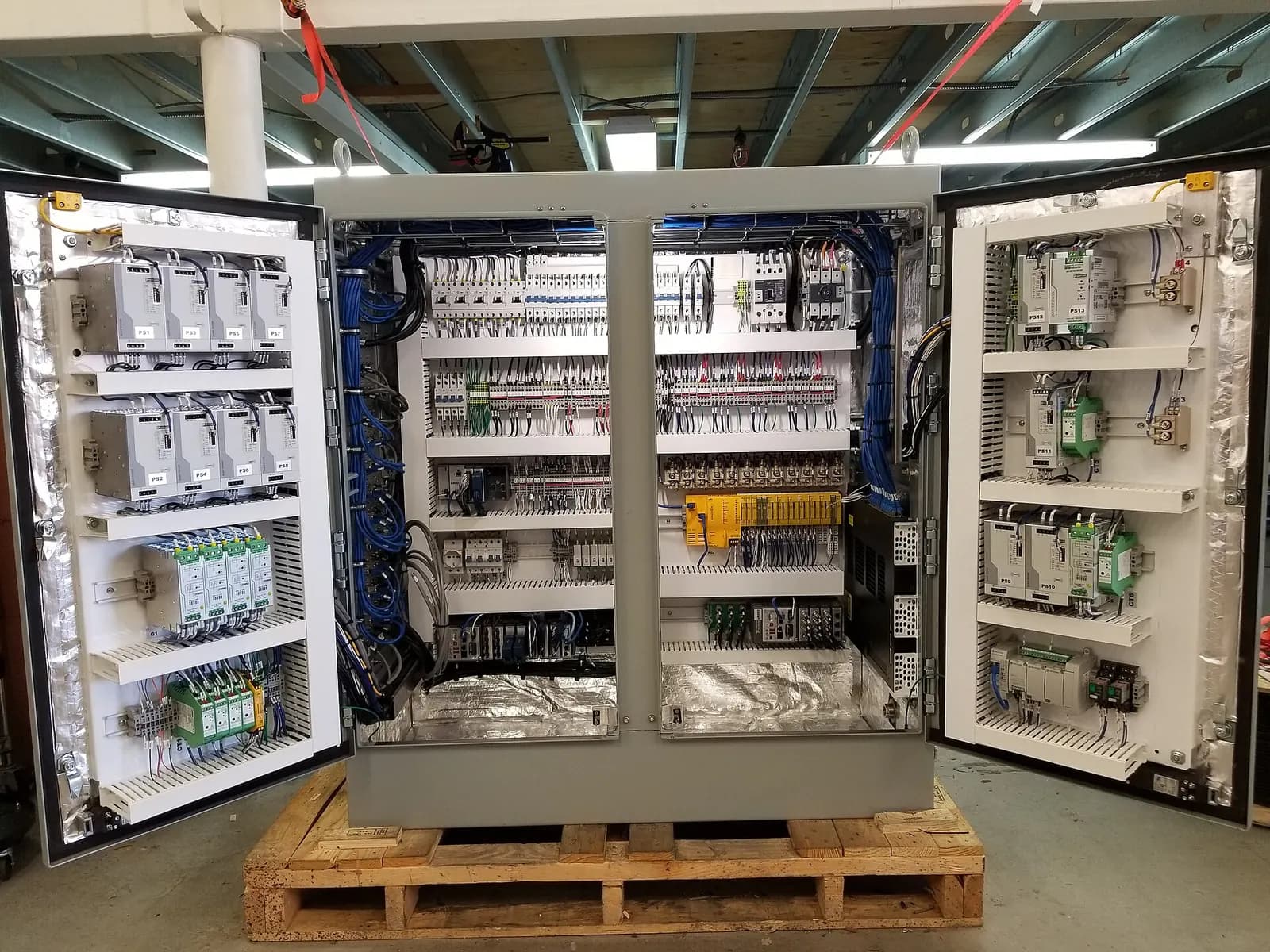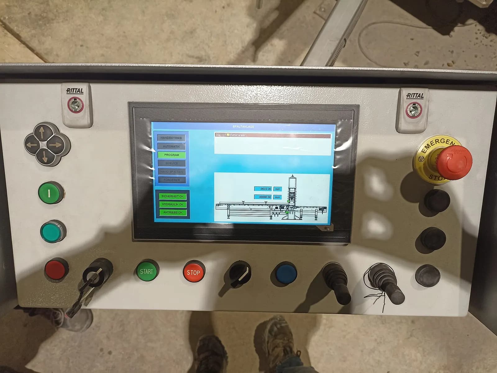
BS EN 60204-1 is the UK edition of IEC 60204-1, Safety of machinery: Electrical equipment of machines, Part 1: General requirements. It covers the electrical, electronic and programmable electronic equipment of machines, from the point where the supply connects to the machine. If you design, build, modify or buy industrial machinery in the UK, it is the standard your control panels and wiring are judged against.
The current international base edition is the sixth, published in 2016, which replaced the 2005 edition; the IEC webstore now lists a consolidated version including Amendment 1 of 2021. It applies to machines not portable by hand while working, including groups of machines working together. Always check which edition your customer or project specification calls up.
Why BS EN 60204-1 matters legally
Standards are generally voluntary. The law in Great Britain is the Supply of Machinery (Safety) Regulations 2008 for those who place machinery on the market, and the Provision and Use of Work Equipment Regulations 1998 (PUWER) for employers using it. Designing to a designated standard is the usual way to show that the relevant essential requirements are met. The government publishes the list of designated standards for machinery, last updated in August 2026. Our UKCA marking guide explains how this fits with conformity marking.
The parts of BS EN 60204-1 that cause most problems
| Topic | What the standard is after | Common shortfall |
|---|---|---|
| Supply disconnecting device | A lockable means to isolate the machine | Isolator that does not isolate all supplies |
| Protective bonding | All exposed conductive parts bonded | Doors and covers not bonded |
| Stop functions | Defined stop categories for each stop | Stop category never decided |
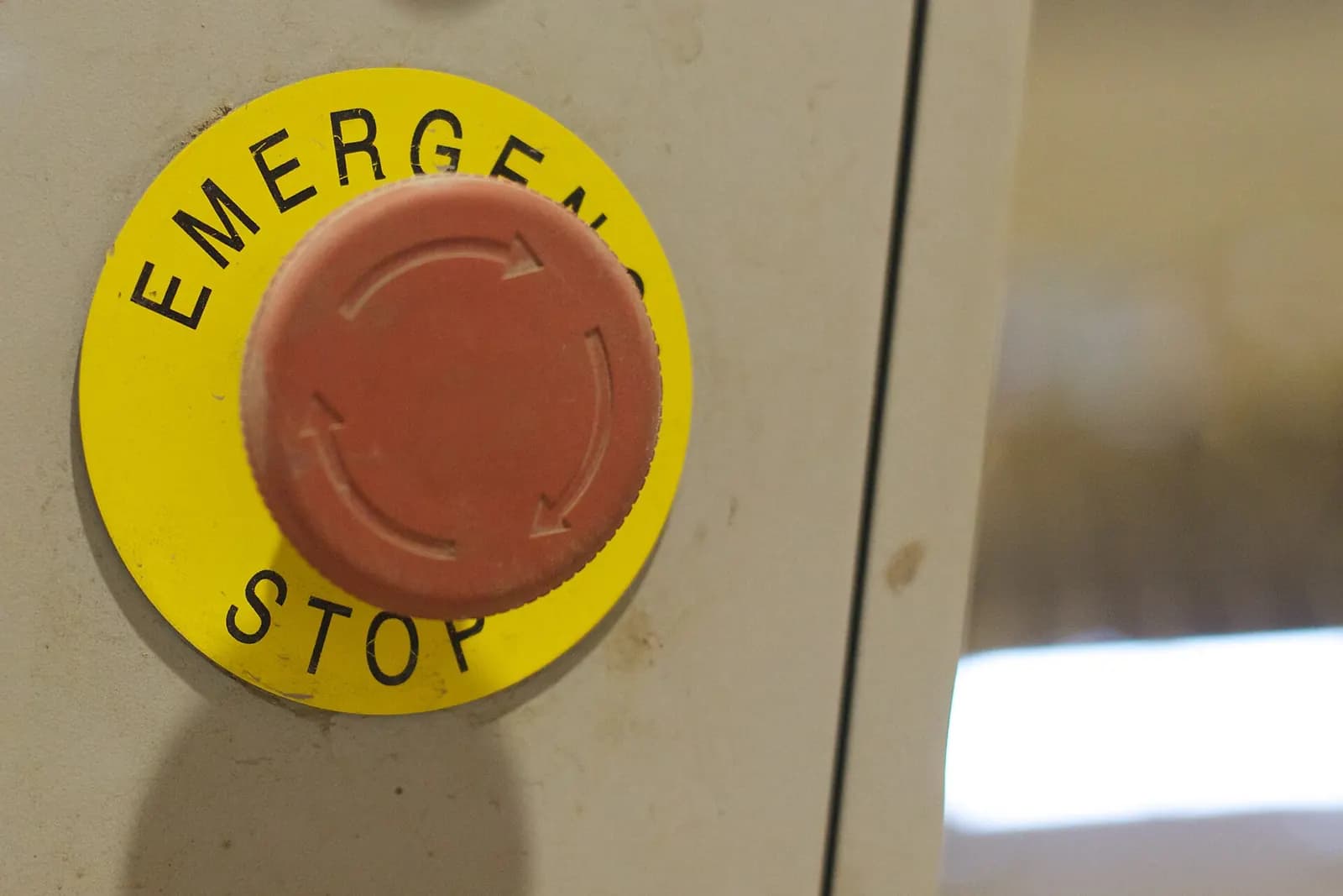
| Emergency stop | Overrides other functions, latches, needs reset | Reset restarts the machine |
| Control circuits | Suitable supply and protection | Unprotected control transformer outputs |
| Documentation | Drawings, manuals and test records | No verification test records |
Stop categories, simply
The standard defines three stop categories, and every stop function on a machine should be assigned one based on the risk assessment.
- Category 0: stopping by immediate removal of power to the actuators. An uncontrolled stop.
- Category 1: a controlled stop with power available to bring the machine to a stop, then power removed.
- Category 2: a controlled stop with power left available to the actuators.
An emergency stop must be category 0 or 1. Category 1 is common on drives and robots, because a controlled ramp-down can be faster and safer than letting a heavy axis coast. Write the chosen category into the design, and make sure the safety circuit and drive settings actually deliver it.
Emergency stop mistakes we still see
- Resetting the emergency stop restarts the machine. The reset should only allow a separate, deliberate start.
- The emergency stop is wired only into the PLC, with no safety-rated function behind it.
- Stop buttons are out of reach of the operator positions identified in the risk assessment.
- The emergency stop is used as the normal way to stop the machine, which hides wear and abuse.
Why the Series Emergency Stop Circuit Failed
RealPars
This video is hosted on YouTube. Playing it loads content from Google, which may set cookies.
Watch on YouTubeSoftware and PLCs under BS EN 60204-1
PLCs control almost every modern machine, but safety functions should not rely on standard PLC logic alone. Safety functions need components and software that meet the performance or integrity level from the risk assessment, using standards such as EN ISO 13849-1 or EN 62061, typically through a safety relay or safety PLC. Standard PLC logic then handles everything else. Keep the two clearly separated in the design and in the code.
Verification: the tests people forget
The standard expects the electrical equipment to be verified before it is put into service, with results recorded. On most projects that includes continuity of the protective bonding circuit, insulation resistance, functional tests of the safety and control circuits, and other checks appropriate to the machine. These records are part of the technical file and are often requested years later after an incident.
Panel design details that inspectors notice
Beyond the headline clauses, a few details reliably show whether a panel was designed with the standard in mind: wire identification that matches the drawings, colour conventions applied consistently, enough spare space and terminals for future changes, control circuits supplied through a transformer with proper protection, and clear warning labels where parts stay live after isolation. None of these is expensive at design stage. All of them are expensive to fix after the panel is built.
Existing machines and modifications
When you modify a machine, for example adding a robot or replacing an obsolete PLC, the modified parts should meet current requirements, and you should check that the change has not introduced new hazards. HSE explains on its machinery and CE/UKCA page that modifications so extensive that the item is basically a new machine need a full conformity assessment. For control upgrades, our S7-300 to S7-1500 migration guide shows how to plan the change.
Where Wartens helps
We design control systems and PLC software for UK machinery to BS EN 60204-1, working with your safety and CE or UKCA partner on the risk assessment and safety functions. We hand over drawings, code and test documentation in a form your maintenance team can use.
Next step
If you are building or modifying a machine, send us the risk assessment and existing drawings. We will return a scope for electrical and control design through our automation engineering service. Read more on the UK market page, or contact us.