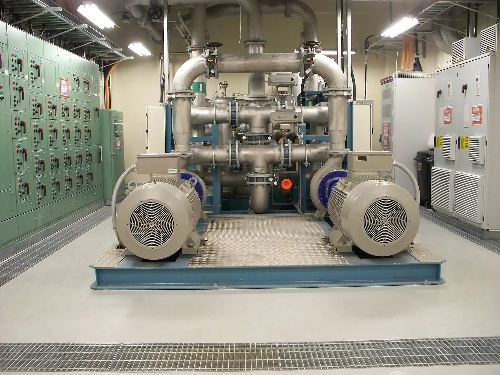
Predictive maintenance sensors measure the physical symptoms of developing faults, such as vibration, temperature, current, ultrasound or oil condition, so that maintenance is done when the data says a component is degrading rather than on a fixed calendar. The choice of sensor should follow the failure modes you want to catch. Fit vibration sensors for bearings and imbalance, current monitoring for motor and load problems, temperature for electrical and lubrication faults, and oil analysis for gearboxes.
The economic case is well documented. The US Department of Energy's FEMP Operations and Maintenance Best Practices Guide estimates that a functional predictive maintenance programme can save 8% to 12% over preventive maintenance alone, and cites industry surveys of 70% to 75% fewer breakdowns and 35% to 45% less downtime. Those are averages from surveys, not guarantees, but they explain why the approach keeps spreading.
Which predictive maintenance sensors detect which failures
| Sensor | Detects | Typical assets | Notes |
|---|---|---|---|
| Vibration (accelerometer) | Bearing wear, imbalance, misalignment, looseness | Motors, pumps, fans, gearboxes | The workhorse; needs good mounting |
| Temperature (RTD, thermocouple, IR) | Overheating bearings, electrical faults, lubrication loss | Motors, bearings, panels, busbars | Cheap and simple; late warning on its own |
| Motor current (CT, drive data) | Load changes, broken rotor bars, pump wear | Motors on drives or starters | Often free from existing drives |
| Ultrasound | Early bearing friction, leaks, electrical discharge | Bearings, compressed air, switchgear | Very early warning; needs expertise |
| Oil and particle | Wear metals, contamination, oil breakdown | Gearboxes, hydraulics | Online sensors or lab samples |
| Pressure and flow | Pump and filter degradation, leaks | Pumps, hydraulic and air systems | Usually already in the PLC |
ISO 17359, the general guideline for condition monitoring of machines, lists the same families of parameters: vibration, temperature, tribology, flow, contamination, power and speed. Its generic procedure, starting from equipment criticality and failure modes, is a sound way to plan any programme.
Wireless IoT Vibration Sensors for Industrial Monitoring
TE Connectivity
This video is hosted on YouTube. Playing it loads content from Google, which may set cookies.
Watch on YouTubeWhere to mount vibration sensors
- On or as close as possible to each bearing housing, in the load zone
- On a flat, clean, rigid surface; stud mounting gives the best high-frequency response, adhesive pads come next, magnets are for route-based checks
- Radial direction first (horizontal and vertical on larger machines), axial where thrust or misalignment is a concern
- Away from guards, thin covers and cooling fins, which resonate and mislead
Evaluate readings against a recognised method. ISO 20816-1 gives general guidelines for measuring and evaluating machine vibration, using both the magnitude of vibration and its change over time. The change is often the more useful signal: a pump that has run at the same level for a year and doubles in a fortnight needs attention, even if the absolute value is still in an acceptable zone.
Wired, wireless or from the drive?
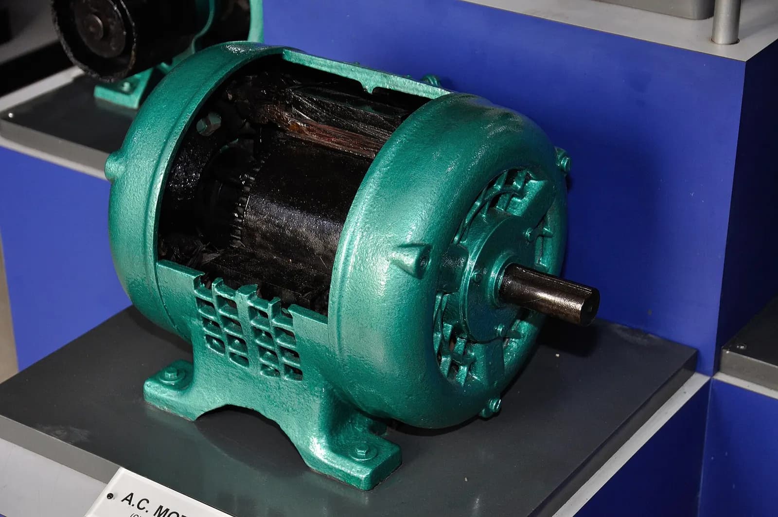
Wired sensors into the PLC or a dedicated monitoring system suit critical, continuously running machines and protection functions. Wireless battery sensors suit large numbers of balance-of-plant assets, where running cables would cost more than the sensors. And variable-speed drives already measure current, torque and speed: reading those through the PLC or OPC UA is often the cheapest first step. IO-Link is worth considering for smart sensors near the machine, because it carries diagnostics and parameters as well as the measurement.
How to start without drowning in data
- Rank assets by the cost of failure: downtime, safety, repair cost and lead time for spares.
- For the top ten, list the likely failure modes and the symptom each produces.
- Choose the sensor that sees that symptom earliest at a reasonable cost.
- Collect baseline data for several weeks under normal operation and different products.
- Set alert thresholds on change from baseline first; add analytics and machine learning once you have history.
- Link every alert to a maintenance action and record what was found, so the model improves.
Data quality matters more than sensor count
The commonest reason predictive maintenance disappoints is not the sensor but the data around it. Time stamps that drift between systems, tags renamed after a PLC change, sensors replaced without recording it and running states that are not logged all make trends meaningless. Record machine state alongside every measurement, so analytics can separate a bearing problem from a product change. Keep an asset register that links each sensor to a specific bearing or motor, and treat a sensor replacement as an event in the data, not just a work order. Finally, make sure maintenance can see the same trend the analytics team sees; trust grows fastest when the technician who opens the bearing can compare what they found with what the data predicted.
Where machine learning helps
Rules and thresholds handle most single-asset cases. Machine learning earns its place where many signals interact, for example a pump whose vibration depends on flow, product viscosity and speed. It needs months of clean, labelled history. That is why getting tag naming, time stamps and maintenance records right in year one matters more than the algorithm.
How Wartens can help
Wartens designs predictive maintenance and IIoT systems as part of our automation work: sensor selection, PLC and SCADA integration, data capture and dashboards, and operational twins with anomaly detection. See automation engineering, our industrial AI service, or tell us which assets keep failing.