A PLC FAT checklist is the list of things the control software must demonstrably do before a machine leaves your works: every sequence, interlock, fault reaction and mode change, tested against agreed criteria and signed by the customer. The quickest way to pass it is to find the logic faults at a desk, weeks earlier, so the factory acceptance test only confirms what you already know. This article gives a checklist you can adapt, a test case format customers accept, and a bench-test routine for the weeks before the FAT.
The structure follows established practice. IEC 62381:2024 defines requirements and checklists for the factory acceptance test (FAT), the factory integration test (FIT), the site acceptance test (SAT) and the site integration test (SIT) for process automation systems (IEC). It was written for the process industry, but its central idea, agreeing scope and responsibilities in advance, applies just as well to a special-purpose machine leaving a works in Swabia.
The three layers of a machine FAT
| Layer | What is proven | Who usually owns it |
|---|---|---|
| Electrical | Protective bonding, insulation, voltage and functional tests per IEC 60204-1 | Panel shop and electrical design |
| I/O | Every input reaches the right tag, every output drives the right device | Commissioning engineer |
| Software and function | Sequences, interlocks, faults, modes, HMI, performance | PLC programmer, signed by customer |
The electrical layer is defined by the verification clause of IEC 60204-1 and is well understood by most panel builders. The I/O layer is mechanical work. The software layer is where FATs overrun, because it is the first time the logic meets something resembling the machine.
The PLC FAT checklist: software and function
- Version identity. The program version, safety program checksum and HMI version are recorded on the test record and match the delivered files.
- I/O list reconciliation. Every tag in the program appears in the I/O list and the drawings, and vice versa. Spare channels are marked as spare.
- Start-up from cold. Power on with no retained data, then with retained data. The machine starts in a known, safe state and does not move on its own.
- Each operating mode. Manual, setup, automatic and any service mode, including what is permitted and what is blocked in each.
- Every sequence step. Each step is entered and left by its documented transition. Timeouts raise a named fault rather than a hang.
- Interlocks and permissives. Each one is tested in its blocking state, not only in its happy path.
- Fault reactions. Simulate each fault, check the machine reaction, the alarm text and the reset path. Acknowledging an alarm must not clear an active fault.
- Safety functions. Demonstrated at FAT, but validated separately under EN ISO 13849. See our guide to safety software validation.
- Loss of communication. Pull the fieldbus cable to a drive or remote I/O station and record what happens.
- Parameters and recipes. Limits are enforced, invalid entries are rejected, changes are logged where required.
- Cycle time and throughput. Measured against the specification, with the measurement method written down.
- Documentation. Functional description, I/O list, alarm list and test record are current at the moment of signature.
Writing test cases a customer will sign
Each line of the checklist becomes one or more test cases with a precondition, an action and an expected result. Keep them short and observable. For example, on a case erector:
| Precondition | Action | Expected result |
|---|---|---|
| Automatic mode, magazine full, guards closed | Force blank sensor B12 off for 3 s | Fault F07 Magazine empty, erector stops at end of cycle, HMI shows alarm |
| Fault F07 active | Press acknowledge with B12 still off | Alarm acknowledged, fault stays active, machine does not restart |
| F07 cleared, B12 on | Press reset, then start | Machine resumes from step 10, not from step 1 |
Bench-testing before the FAT with LADX Monitor
Between writing the logic and standing at the panel there is usually nothing. Monitor, one of the tools in LADX, fills that gap: it runs any saved program at scan speed, lets you force inputs, shows every tag change and records what happened (LADX Monitor).
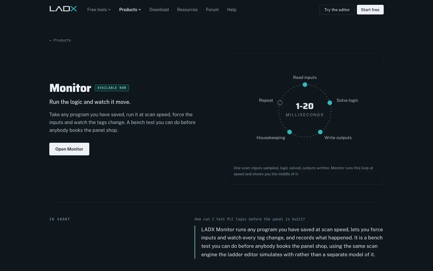
- Open the saved program from the project. Monitor uses the same scan engine as the LADX ladder editor: an output image, edge memory per instruction and timers on elapsed milliseconds.
- Work through the checklist above. Toggle digital inputs, drive analogue values and follow the outputs, which are listed first because they are what a test is judged on.
- Use momentary forcing for push buttons. Buttons spring back the way real ones do.
- Read the timestamped log afterwards to confirm sequence order and timing rather than relying on memory.
- Save the run against the project so it can be attached to the FAT documentation.
Be clear about the limits, as LADX is. Monitor never connects to a controller. It proves the logic does what the logic says; it cannot know that an encoder is wired backwards or that a valve was fitted the wrong way round. A passing run is evidence for a FAT, not a substitute for one.
Factory Acceptance Test Explained - Part 2 | PLC Digital I/O Test
RealPars
This video is hosted on YouTube. Playing it loads content from Google, which may set cookies.
Watch on YouTubeWhen a bench test is not enough
A bench test exercises logic against inputs you choose. It does not model a conveyor that takes 1.8 s to clear a carton or a servo that overshoots. When timing and physical interaction matter, which they do on most special-purpose machines, the next step is virtual commissioning: the real PLC program running against a simulated machine. Our guides to virtual commissioning with PLCSIM Advanced and with TwinCAT explain the set-up. LADX's own commissioning article sets out a sensible order on the day: power and safety circuits first, then I/O point by point, then devices in manual, then sequences (LADX).
Where Wartens fits
Wartens delivers PLC, HMI and safety software for German machine builders as a fixed work package, handed over with the test documentation. See our automation engineering services and virtual commissioning.
Next step: send us your FAT protocol or specification and we will mark which tests can be run before the panel exists. Contact us.