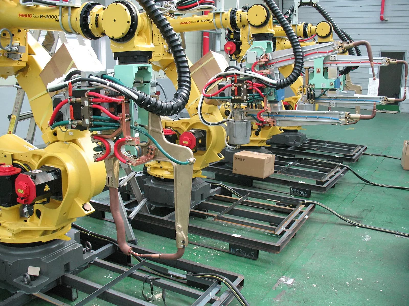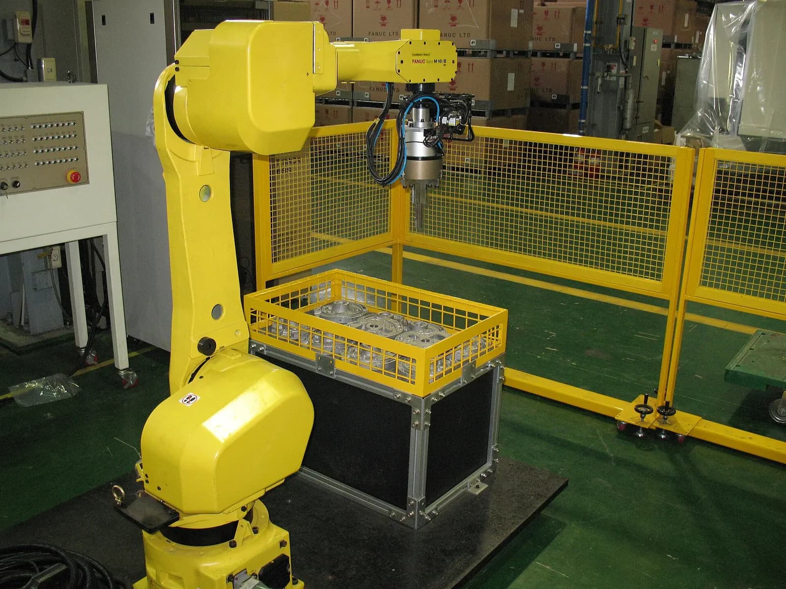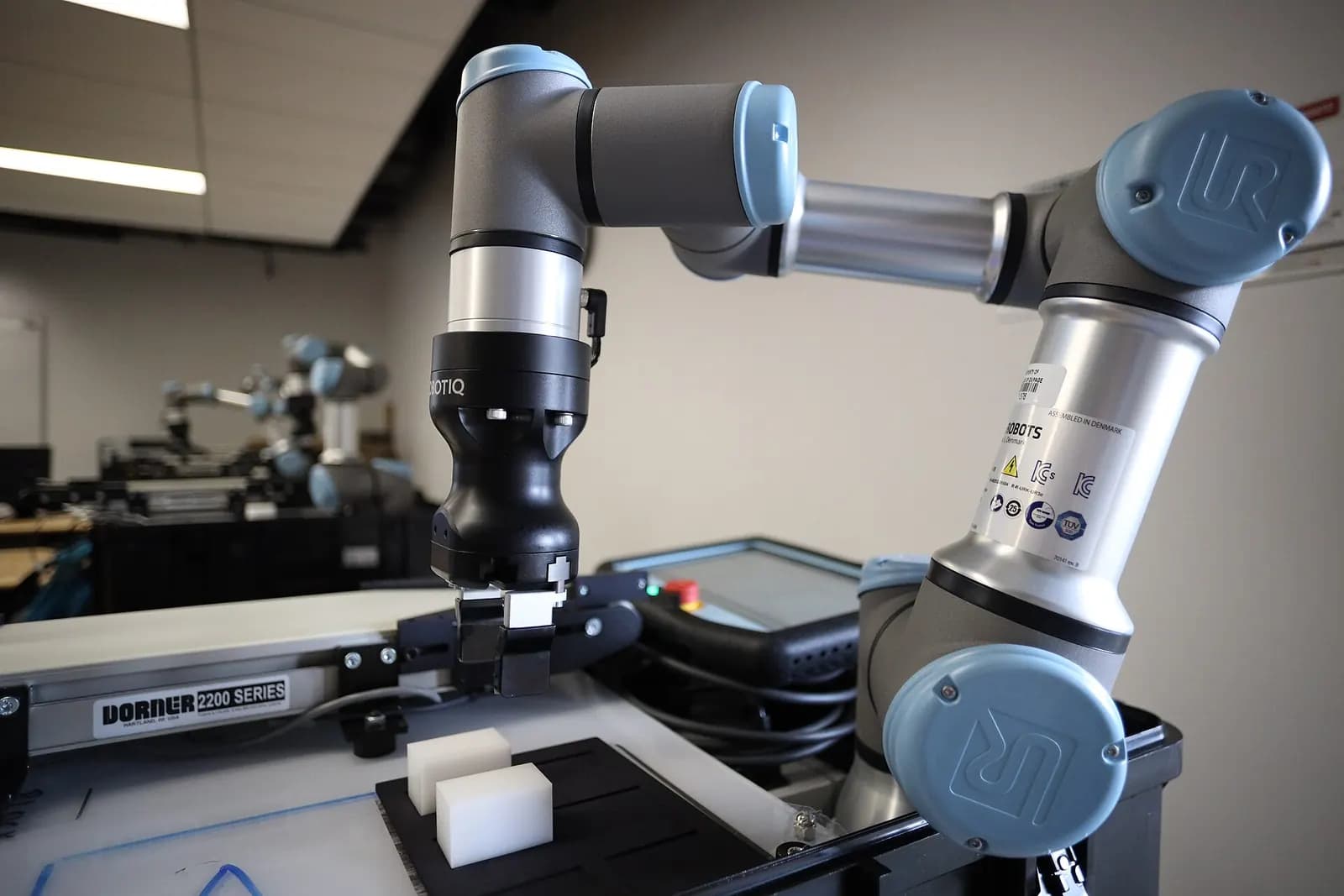
A cobot safety risk assessment looks at the whole collaborative application, not just the robot arm: the tool, the part, the fixtures, the people nearby and every task they do, including setup, cleaning and fault recovery. In the U.S. the reference is now ANSI/A3 R15.06-2025, which brings in the 2025 revision of ISO 10218, with ISO/TS 15066 giving guidance on collaborative operation. A cobot's built-in force limits help, but a sharp knife on a gentle robot is still a sharp knife.
Why this matters now
Collaborative robots made up 43.7% of first-half 2026 robot orders from life sciences, pharma and biomedical customers in North America, and 36.5% in semiconductors and electronics (A3 via automation.com, August 2026). Many of those buyers are installing their first robot. The word "collaborative" on a datasheet is easy to misread as "safe without further work".
A3 makes the point directly: a cobot application still requires a risk assessment (A3, September 2026). OSHA notes that there are no OSHA standards specific to robotics, and that many robot accidents happen during non-routine work such as programming, maintenance, setup and adjustment (OSHA robotics).
The standards, in plain terms
| Standard | What it covers |
|---|---|
| ANSI/A3 R15.06-2025 Part 1 | Industrial robots (the manufacturer's side) |
| ANSI/A3 R15.06-2025 Part 2 | Robot applications and robot cells (the integrator's side) |
| ANSI/A3 R15.06-2025 Part 3 | Use of industrial robot cells (the user's side) |
| ISO/TS 15066 (RIA TR R15.606 in the U.S.) | Collaborative operation, including force and pressure guidance |
| ISO 13849-1 | Design of safety-related control parts and performance levels |
A3 describes R15.06-2025 as the first major revision since 2011, published after nearly eight years of work, with Parts 1 and 2 making functional safety requirements explicit (A3 robotic standards). The international base, ISO 10218-2:2025, covers industrial robot applications and robot cells (ISO). Note that OSHA's robotics standards page may still list older editions, so check which edition your customer or insurer expects.
Cobot Insights UK | How to Setup a Safety Plane | UR20's in Cars | Interviewing Dr. James Law - EP7
Universal Robots
This video is hosted on YouTube. Playing it loads content from Google, which may set cookies.
Watch on YouTubeRunning the assessment, step by step
- Define the application: robot, tool, payload, parts, fixtures, layout, cycle and every person who will be near the cell.
- List the tasks: normal operation, loading, changeover, cleaning, teaching, fault recovery, maintenance.
- Identify hazards per task: impact, clamping between robot and fixture, sharp or hot tooling, dropped parts, unexpected restart.
- Estimate risk before any safeguards, using a consistent method such as the task-based approach in RIA TR R15.306.
- Choose risk reduction: design changes first (rounded tooling, lower forces, more space), then safeguards, then information and training.
- Set the safety functions: speed and separation monitoring, power and force limiting, safety planes, enabling devices, each with a required performance level.
- Validate: measure forces where power and force limiting is used, test every safety function and record the results.
The traps we see most often
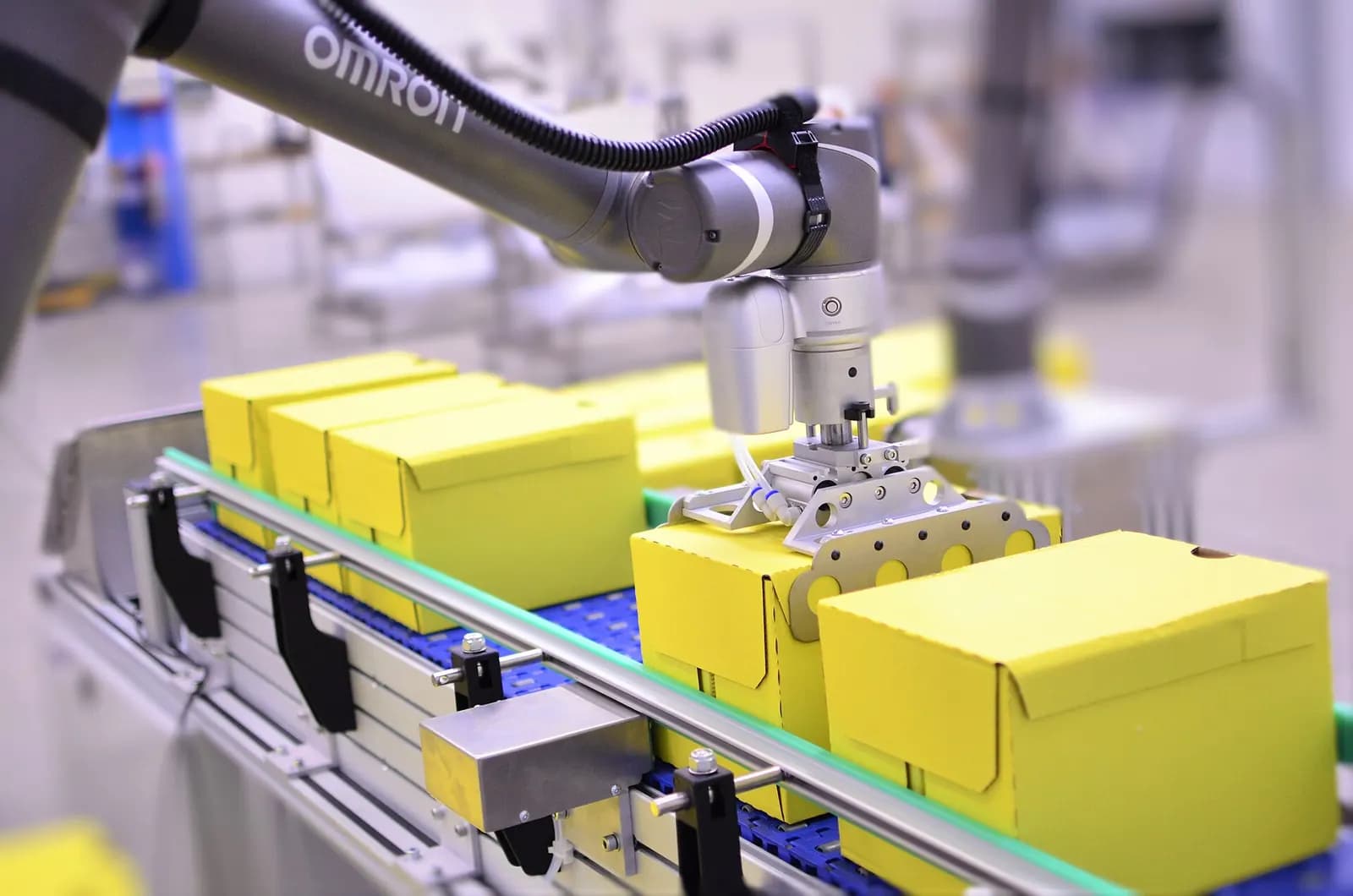
- Assessing the robot, not the tool. A gripper finger, a screwdriver bit or a part edge changes everything.
- Clamping points. Transient contact in open space may be acceptable. Being trapped against a table or a fixture is a different case.
- Speed creep. Cycle-time pressure leads to higher speeds after acceptance. Lock safety settings and record checksums.
- Forgotten tasks. Cleaning and changeover often happen with the robot in a different mode, with different risks.
- No validation record. If forces were not measured, the assessment rests on assumptions.
Power and force limiting versus speed and separation
Most cobot applications rely on one of two collaborative methods, or a mix. Power and force limiting accepts that contact may happen and keeps it below levels that would injure. It needs low speeds, padded or rounded tooling and measured forces, and it rarely suits heavy or sharp parts. Speed and separation monitoring uses scanners or cameras to slow the robot as people approach and stop it before contact. It allows faster cycles when nobody is near, but needs careful sensor placement and stopping-distance calculations.
Our advice: decide the method in the first design review, because it changes the layout, the tooling and the cycle time. Many projects start with power and force limiting because it sounds simpler, discover that the gripper or part makes it impossible, and redesign late. A short assessment early avoids that.
Where the PLC comes in
Most cobot cells are not standalone. A PLC handles part flow, area scanners, door switches and the line interface, often over a safety network. The safety functions are only as good as the logic and wiring that connect them. That is why we design the safety I/O and interlocks with the risk assessment in hand. See PLC and robot integration for the signals involved, and offline robot programming for how cobot paths are planned to keep clear of clamping points.
We program and simulate cobot and robot cells for U.S. clients and design the PLC interlocks around the risk assessment. The assessment and sign-off remain with the integrator or user responsible for the cell. Learn about our robot cell programming service, or contact us about a cell you are planning.