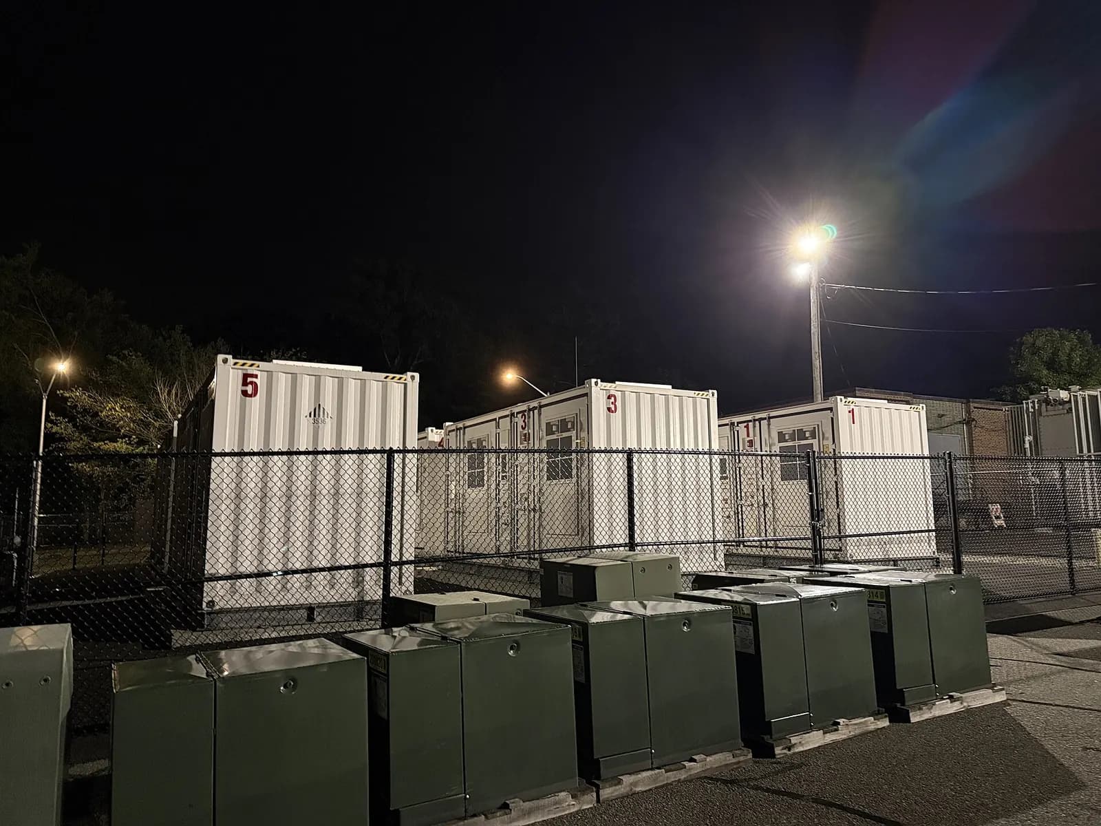
NFPA 855 is the U.S. standard for the installation of stationary energy storage systems. It covers how battery systems are listed and tested, how they are spaced and protected, and how fires and explosions are detected, contained and managed. For controls engineers the point is simple: many of its protections rely on the battery management system, the site controller, the fire detection system and the SCADA system working together and failing safely. The current edition is 2026.
Where NFPA 855 stands in 2026
NFPA lists the 2026 edition as current, with the next edition planned for 2029 (NFPA 855 standard development). Local fire codes adopt editions at different times, so the edition that applies to your site depends on the jurisdiction. The U.S. Department of Energy's Energy Storage Safety Strategic Plan names NFPA 855 as the installation standard and notes that utility-scale battery storage grew from about 200 MW at the end of 2013 to about 9 GW at the end of 2022 (DOE, April 2024).
The safety record has improved a lot. EPRI's failure incident database, started in 2021, reports that the failure rate per deployed capacity dropped by 99% from 2018 to 2025 (EPRI BESS Failure Incident Database). Better cells, better listing and better installation rules all contributed. Controls are part of that story.
UL 9540 and UL 9540A: listing and fire testing
UL 9540 is the standard for energy storage systems and equipment, and its evaluation includes charging and discharging, protection, controls and communication (UL Solutions). UL 9540A is the test method for thermal runaway fire propagation, run at cell, module, unit and installation level. It is used when a system exceeds limits in NFPA 855, NFPA 1, the IFC or the IRC, and the 6th edition adds an installation-level test (UL 9540A).
Ask the battery vendor for the UL 9540 listing details and the UL 9540A report early in design, and make sure the site layout, ventilation and detection concept match what was tested. For controls engineers, the key consequence is that the listed system includes its controls. Changing BMS settings, protection thresholds or control firmware outside the manufacturer's instructions can take the system outside the configuration that was tested. Treat those settings as safety settings.
UL 9540A, Ed. 6, Advances Large-Scale Fire Testing for BESS
UL Solutions
This video is hosted on YouTube. Playing it loads content from Google, which may set cookies.
Watch on YouTubeControls functions that support NFPA 855 safety
| Function | What the controls must do |
|---|---|
| Battery protection | BMS trips on over-voltage, under-voltage, over-temperature and over-current, and the site controller respects BMS limits |
| Detection | Gas, smoke and temperature alarms reach the site controller and SCADA without delay |
| Shutdown | Emergency stops and fire signals open the right breakers and stop inverters in a defined order |
| Ventilation and explosion control | Interlocks between detection, ventilation and access doors work as designed |
| Monitoring | Alarms and data reach a staffed location, with history kept for investigation |
| Fail-safe behavior | Loss of communication or power leads to a safe state, not to running blind |
Where controls go wrong
- Alarms that nobody sees. Off-gas or thermal alarms routed to a local HMI at an unstaffed site. Route them to the monitoring center and to the fire alarm panel as designed.
- Stale data. A site controller that keeps dispatching on the last good BMS value after a communication loss.
- Shutdown sequences tested once. E-stop and fire shutdown paths should be retested after every software or wiring change.
- Undocumented settings changes. BMS or inverter settings changed during troubleshooting and never recorded.
- No event history. Without time-synced logs, an incident cannot be reconstructed.
Testing shutdown logic without a fire
Safety-related controls are only trusted when they have been tested, and nobody wants to test them for real. The practical answer is a structured functional test of every cause-and-effect line: simulate each detector input, confirm each output in the defined order and time, and record the result. Do it at factory acceptance with the vendor's equipment, again at site acceptance with the fire alarm system connected, and again after any change to the logic or wiring.
Much of the site controller and SCADA behavior can be tested earlier still, against a simulation of BMS, inverters and detectors. That catches the logic errors, such as a missing interlock or a wrong alarm priority, before the hardware arrives. The physical test on site then confirms wiring and devices rather than discovering design mistakes.
Record every test with date, software versions and results, and keep the records with the site documentation. They are what an investigator, insurer or fire official will ask for after any incident.
Working with the authority having jurisdiction
Fire officials review storage projects closely, and they often ask how the system will be monitored and how first responders will know what is happening. Good controls documentation helps: a clear cause-and-effect matrix for detection and shutdown, a description of remote monitoring and alarm routing, and screens that show emergency status at a glance. Prepare these early. They are also the documents your operations team will need for the next twenty years.
Our engineers build SCADA, monitoring and controller logic for storage and solar-plus-storage sites. Fire protection design and code compliance stay with the project's fire protection engineer and the AHJ. Read BESS SCADA design, see our battery storage controls service or contact us about a project.